Table of contents
- Table of contents
- Introduction
- Right side - Plate
- Right side - thumb cluster
- Left side - Plate
- Left side - thumb cluster
Introduction
For the keyboard to work, we need to install some components on the PCBs.
We will start by installing the diodes. If you have per-key RGB the components for that came in a separate bag - you can set them aside, we will install them in the next section.
There are 2 sides of the keyboard: left, and right. All the PCBs are reversible, so make sure to follow the steps carefully to make sure you’re installing the components correctly.
Right side - Plate
Right side - Plate - Required parts
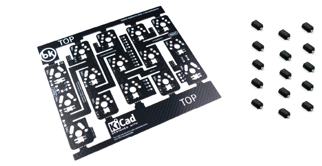
For the following step, please prepare:
- Plate PCB (x1)
- diode (x15)
Your PCBs might look slightly different than the pictures, depending on when you ordered your kit. The installation procedure is the same.
Right side - Plate - placing the PCB
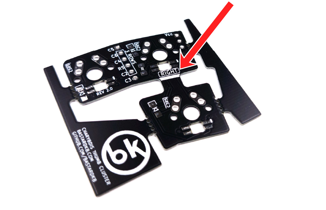
- All the PCBs are reversible, so first let’s make sure we install the components on the correct side
- Place the plate PCB on your working surface, and make sure the “RIGHT” label is visible.
- Use the picture below for reference.
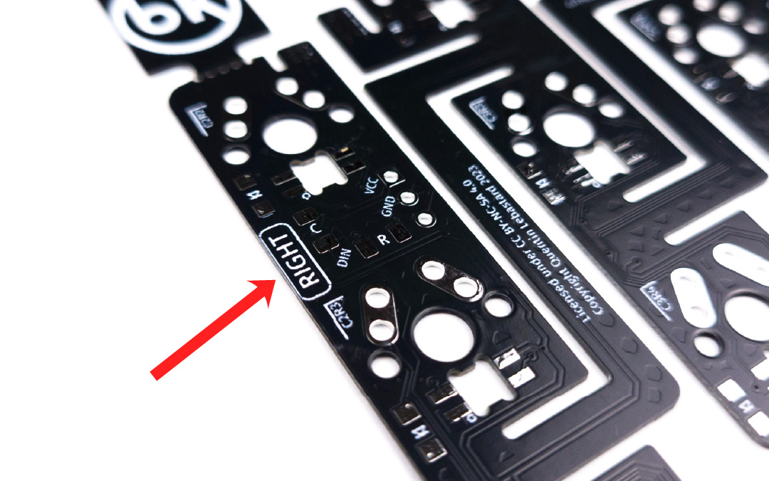
From now on, we will refer to this plate as the “Right PCB”.
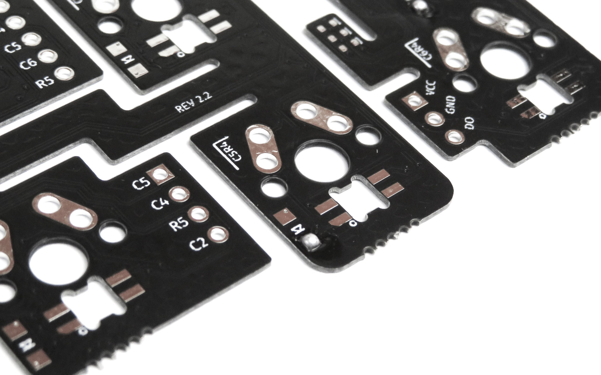
Right side - Plate - installing the diodes
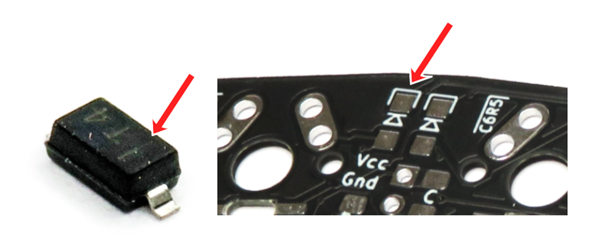
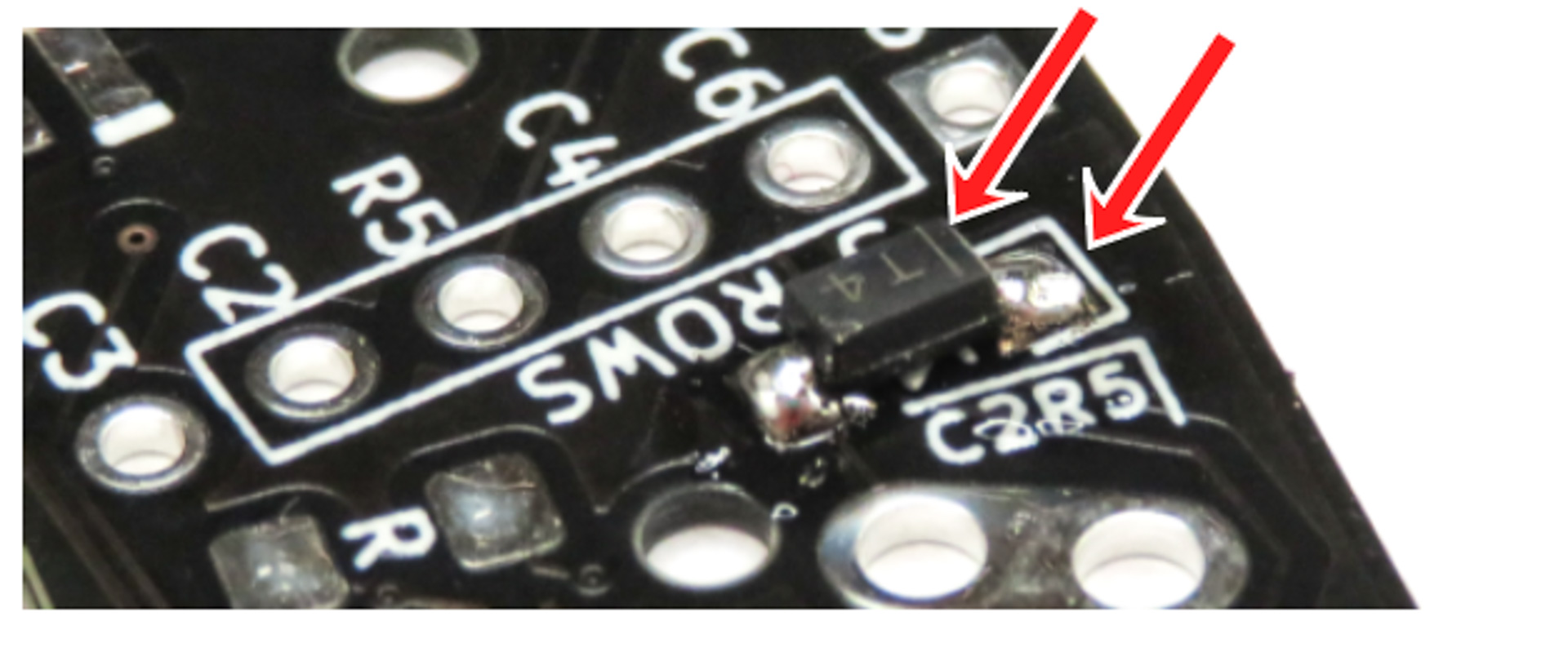
On the plate PCB, we need to install a total of 15 diodes. They go on the footprints with 2 pads (see pictures below).
These diodes need to be installed in a specific way, or they will not work! Read the following carefully.
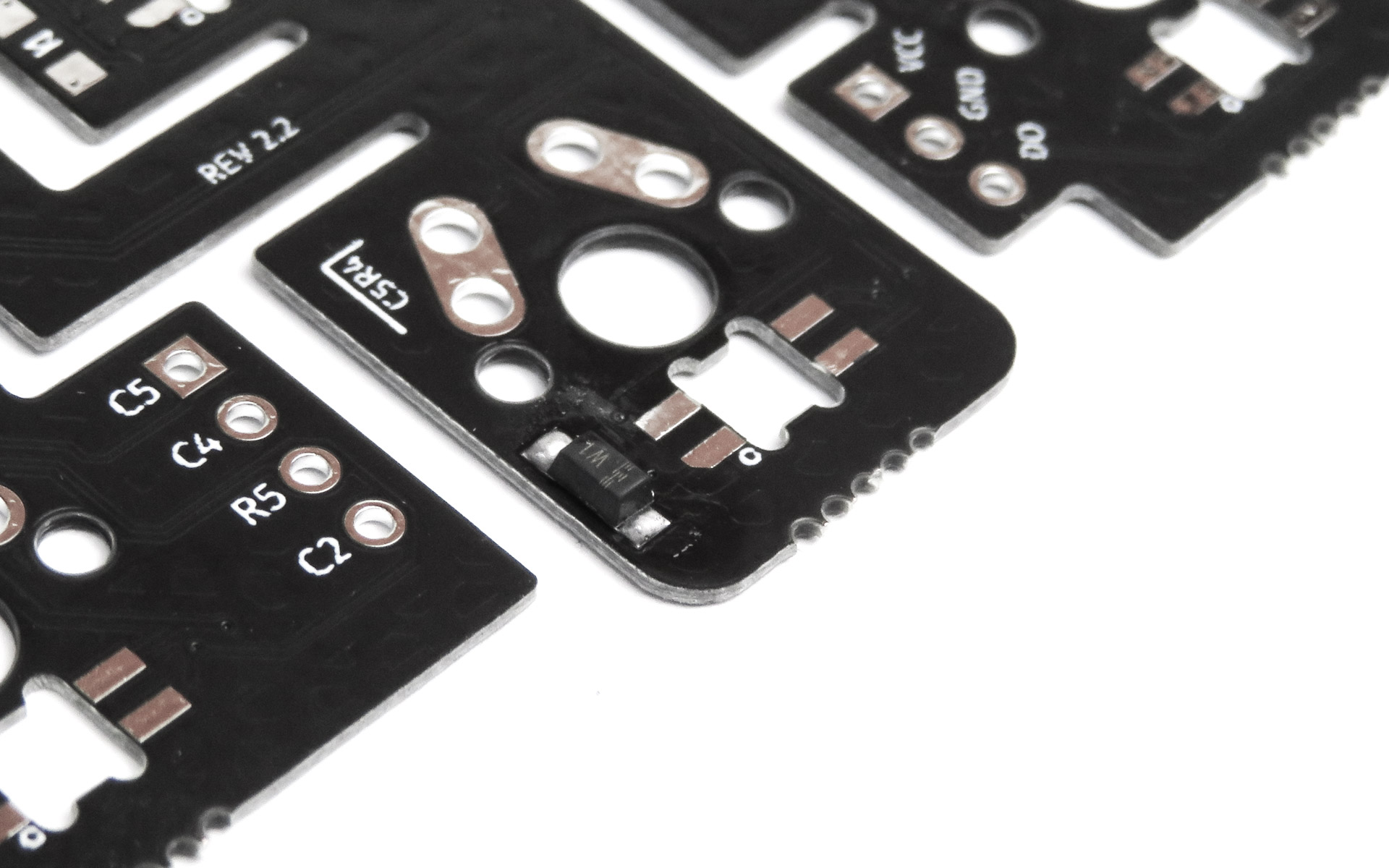
- Inspect the 2-legged diodes: there is a horizontal line on them
- This line needs to be aligned with the white markers on the PCBs
- If you do not align them, the keys will not work
In the following section, we detail some tips on how to install diodes. You can also use this technique to install capacitors and resistors. If you are familiar with it, feel free to install the diodes and skip ahead to the next section.
- Using a soldering iron, put some soldering tin on one pad
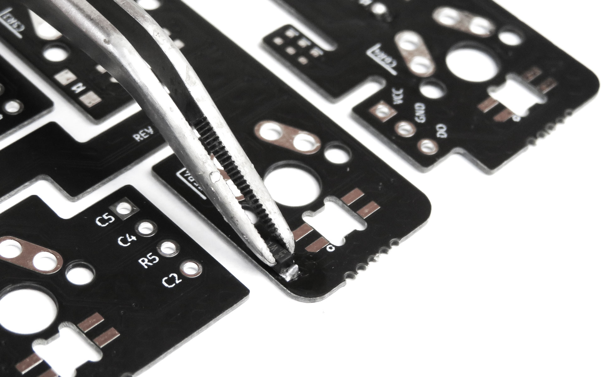
- Using tweezers, install the diode, with one of its pins on top of the pad you just tinned
- Melt the soldering tin, while still holding the diode in place. The soldering tin will “melt around” the diode’s pin
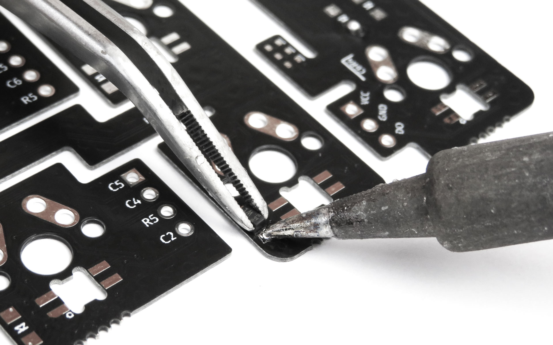
- Once the solder melted, remove the soldering iron
- Do not let go of the diode until the soldering tin is solid again
- After the soldering tin has solidified, you can let go of the diode
- The diode should now not move at all
- Solder the other pad
Do the same for the 15 diodes.
Right side - thumb cluster
Right side - thumb cluster - required parts
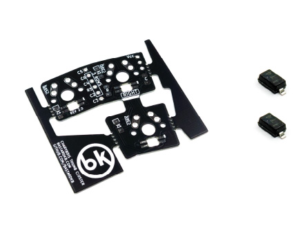
For the following step, please prepare:
- 3-key thumb PCB (x1)
- 2-leg diode (x2)
If you are preparing a left-handed Charybdis Nano, use the other 3-key thumb cluster PCB in this step instead.
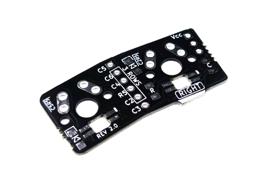
Right side - thumb cluster - preparing the PCB
Because the Charybdis Nano has only 2 thumb keys, we need to cut the PCB.
- locate the while line on the PCB
- cut the PCB along the line
- also remove the outer part of the PCB, by cutting the mouse bites
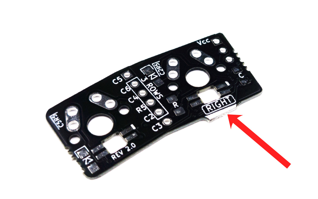
Right side - thumb cluster - placing the PCB
- Place the plate PCB on your working surface, and make sure the “RIGHT” label is visible
- Use the picture below for reference
Right side - thumb cluster - installing the diodes
On the thumb cluster PCB, we need to install a total of 2 diodes. They go on the footprints with 2 pads (see pictures below).
- Use the same method as previously to install the diodes
- Take care to align the line with the marks on the PCB
Left side - Plate
Left side - Plate - required parts
Now that we finished preparing the right side, we will continue and prepare the left side.
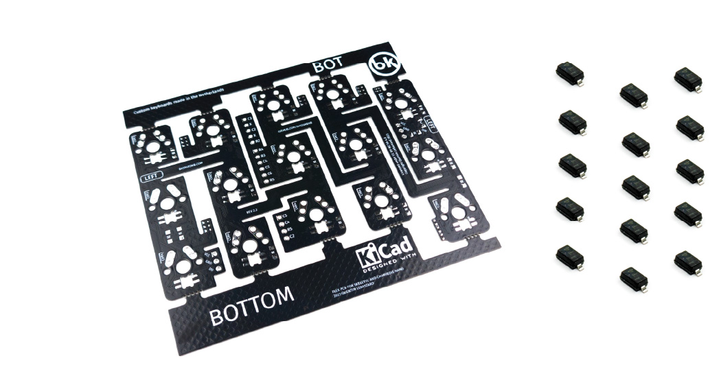
For the following step, please prepare:
- Plate PCB (x1)
- diode (x15)
Left side - Plate - placing the PCB
- Place the plate PCB on your working surface, and make sure the “LEFT” label is visible
- Use the picture below for reference.
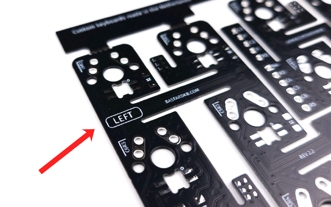
From now on, we will refer to this plate as the “Left PCB”.
Left side - Plate - installing the diodes
Just like previously, install the diodes.
Left side - thumb cluster
Left side - thumb cluster - required parts
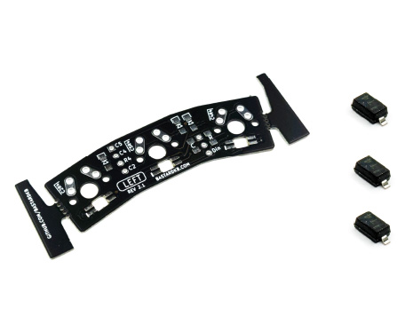
For the following step, please prepare:
- 3-key thumb PCB (x1)
- diode (x3)
If you are preparing a left-handed Charybdis, use the other 3-key thumb cluster PCB in this step instead.
Left side - thumb cluster - placing the PCB
- Place the plate PCB on your working surface, and make sure the “LEFT” label is visible
- Use the picture below for reference.
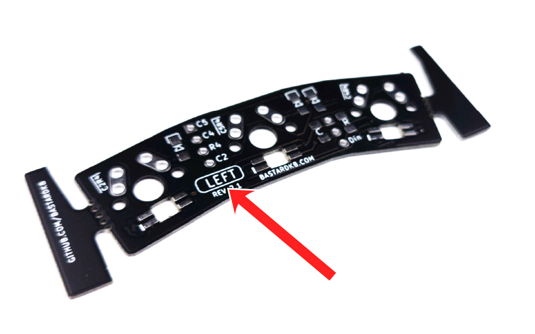
Left side - thumb cluster - installing the diodes
Just like previously, install the diodes.