Table of contents
- Table of contents
- Preparing the 3d holder assembly
- Spin the ball
- Soldering the sensor PCB to the Splinky Shield
- Placing the sensor PCB
- Installing the 3d holder assembly
- Installing the sensor PCB and protective cover
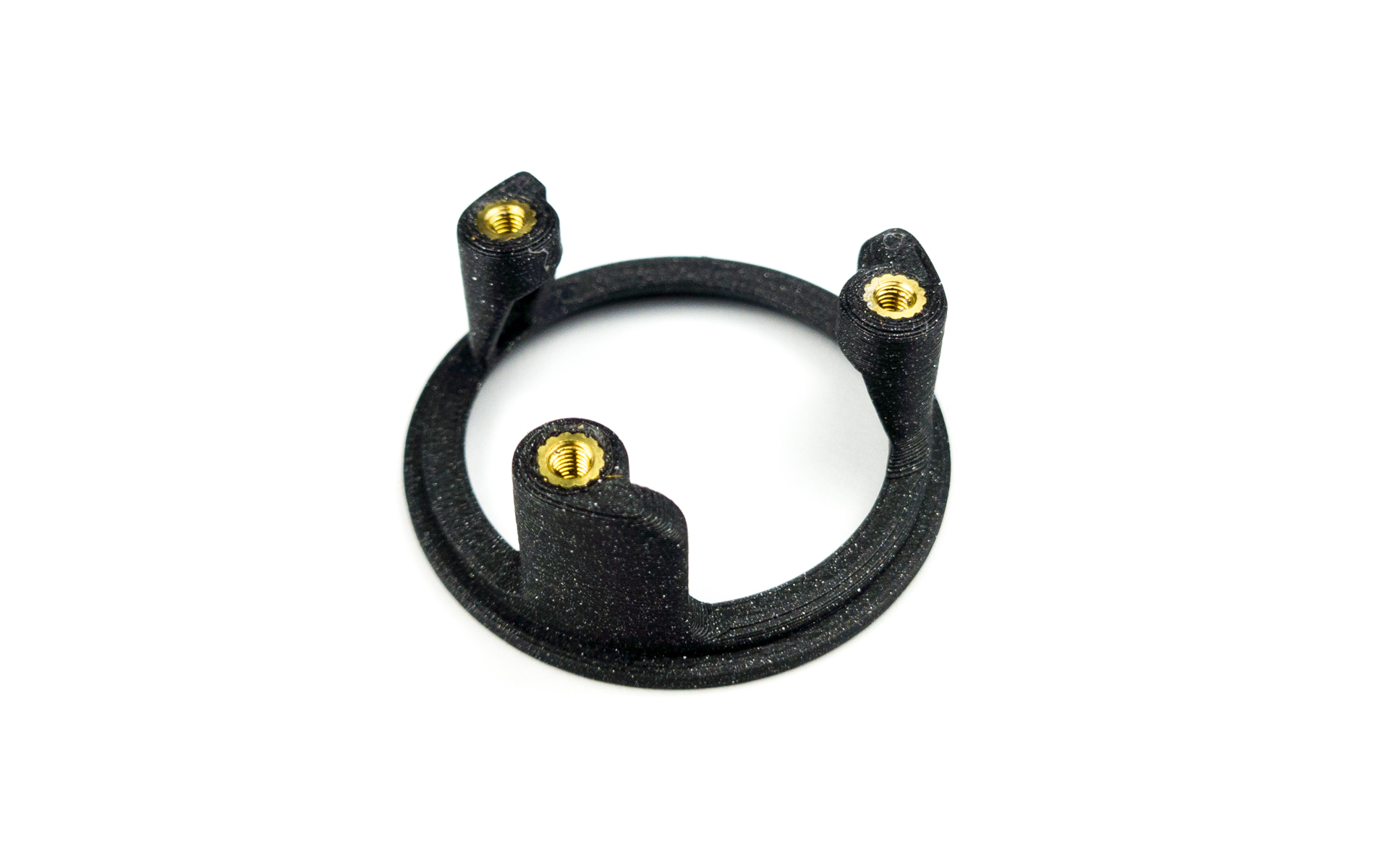
Preparing the 3d holder assembly
Top housing - screw inserts
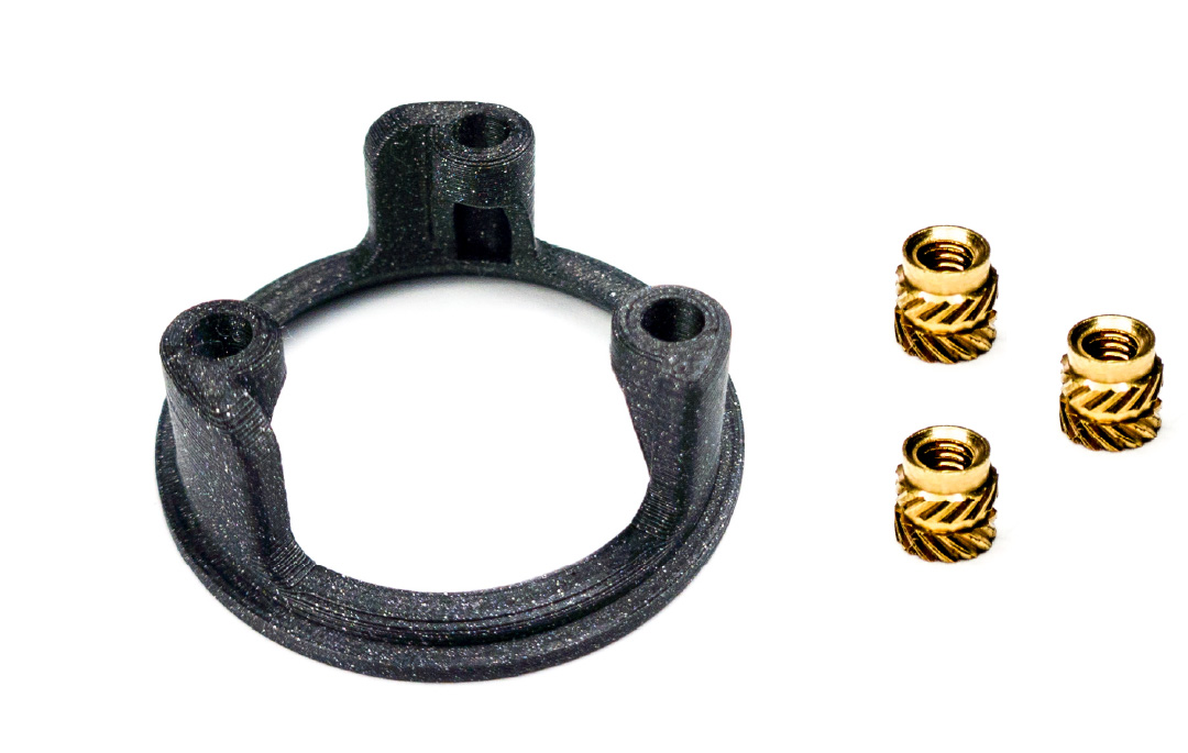
For the following step, please prepare:
- 3d printed top housing (x1)
- M3 screw insert (x3)
There are 2 sizes of screw inserts in your kit. In this step, we will use the small ones.
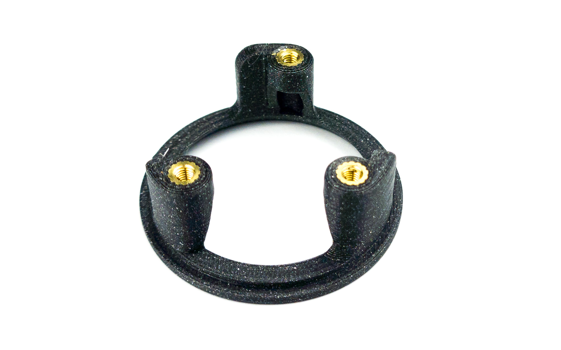
- Install the 3 screw inserts
- Use the same method as for the case
- Let gravity do the work
- Push it 2/3 of the way in, then flip it and push flush against a flat surface
Bottom housing - screw inserts
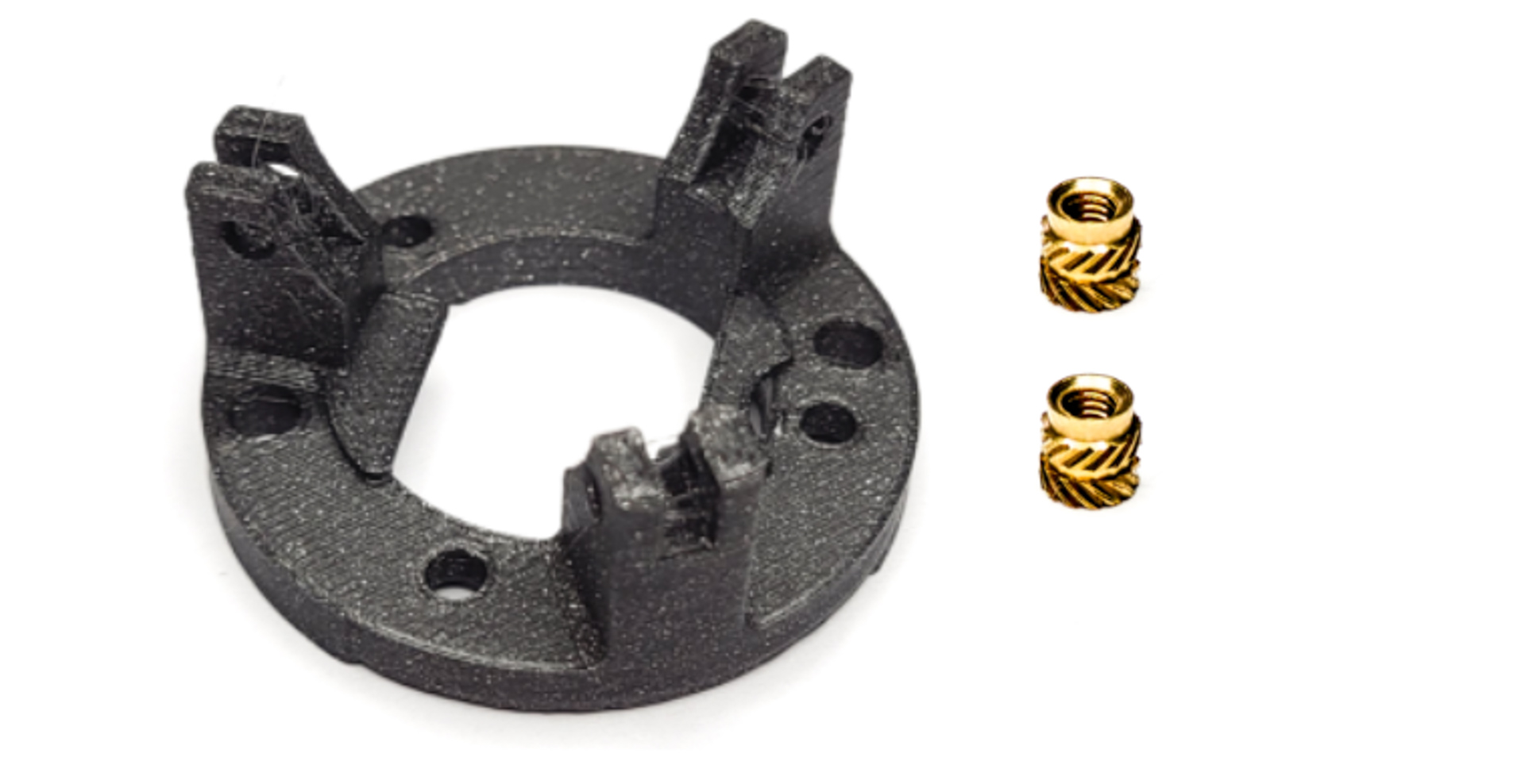
For the following step, please prepare:
- 3d printed bottom housing (x1)
- M3 screw insert (x2)
There are 2 sizes of screw inserts in your kit. In this step, we will use the small ones.
Depending on your kit, the bottom housing might look slightly different. The process to prepare it and install it is the same.
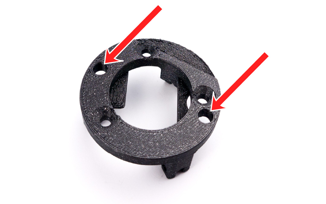
- Inspect the bottom housing: there are 3 holes with a chamfer, and 2 holes without.
- For the screw inserts, we will use the 2 holes without chamfers
- Use the picture below for reference
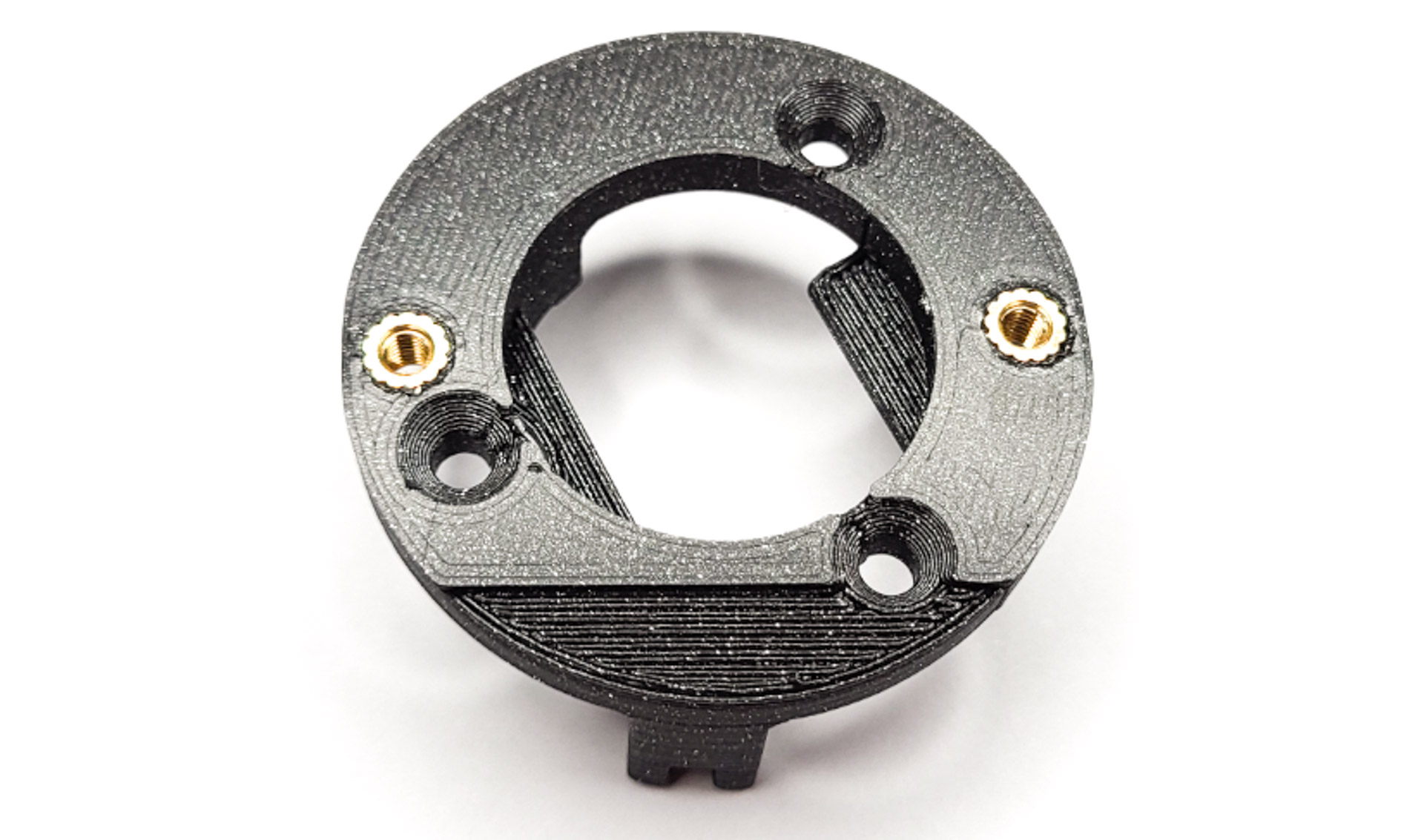
- Install the 2 screw inserts
- Use the same method as for the case
- Let gravity do the work
- Push it 2/3 of the way in, then flip it and push flush against a flat surface
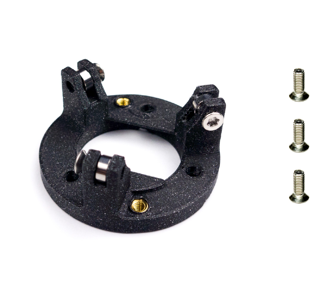
Bottom housing - bearings
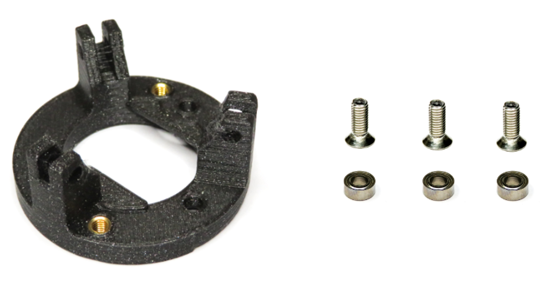
For the following step, please prepare:
- 3d printed bottom housing (x1)
- M3 screw (x3)
- M3 bearing (x3)
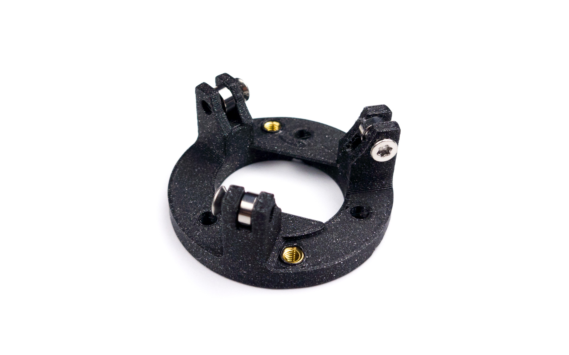
For each of the 3 bearings:
- Install the bearing in its spot
- Screw in the M3 torx screw
- Make sure it can rotate freely. If not, unscrew by half a turn and check again
Spin the ball
- If you printed the case yourself, the bearings might scratch a bit against the 3d print and not roll correctly
- Rest the trackball on top of the 3 bearings
- Place your palm on top of the trackball
- Applying gentle pressure, make a circle movement, make sure you can hear the bearings rotating
- Do this for around 30 seconds, or until the trackball feels smooth
Soldering the sensor PCB to the Splinky Shield

For the following step, please prepare:
- keyboard assembly
- sensor PCB assembly
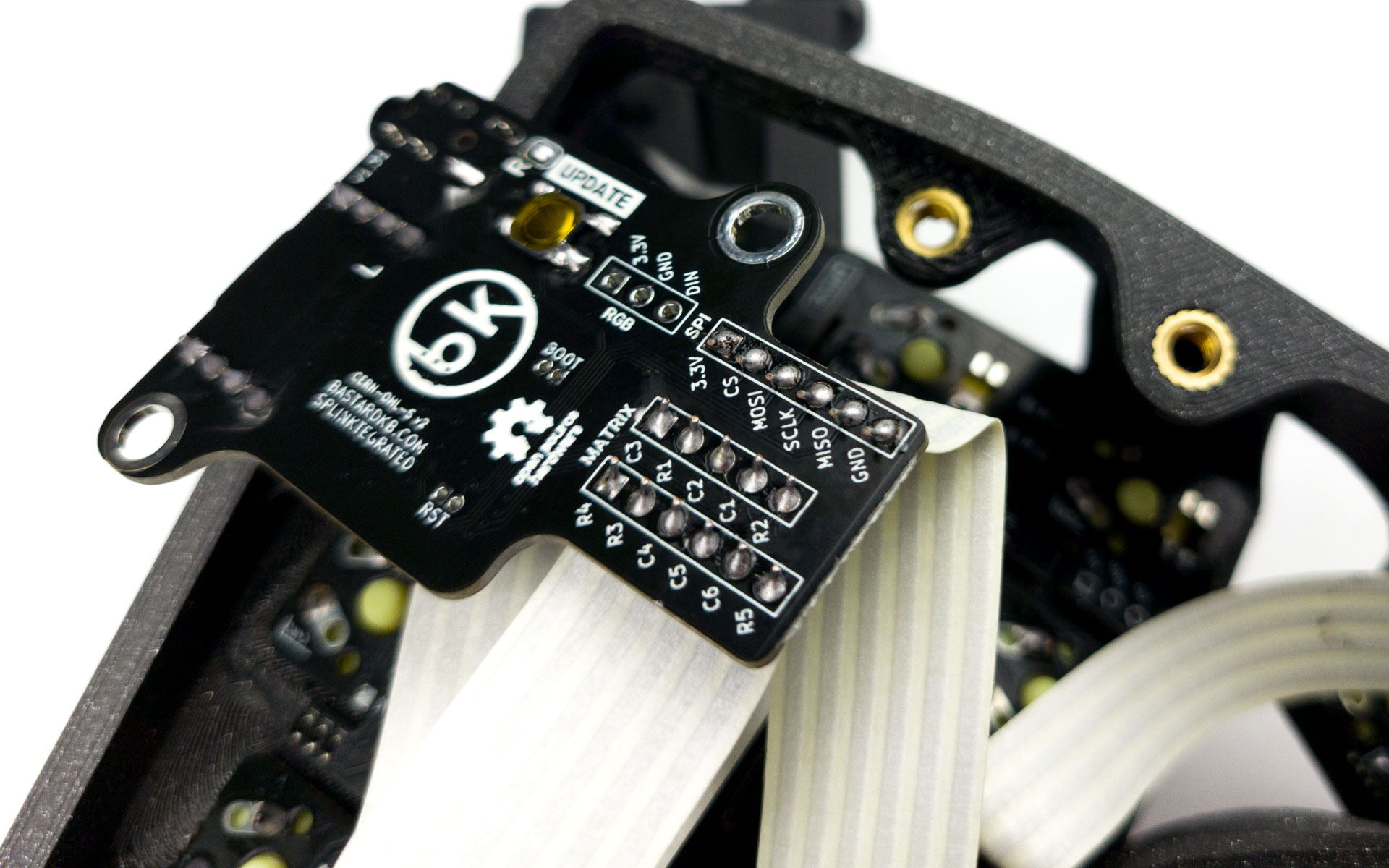
Inspect the Splinky shield: there is a SPI header, that we need to connect to the sensor PCB.
- match the 3v3 with the 5V
- the rest of the pins will align
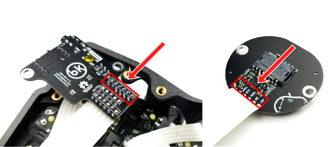
Install the cable and solder it just like the other ones. Make sure to match the labels.
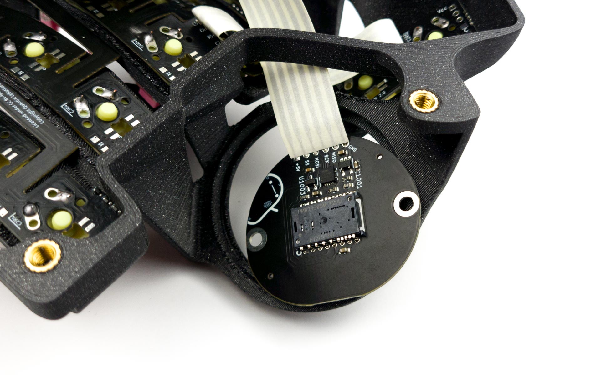
Placing the sensor PCB
Remove the lens: 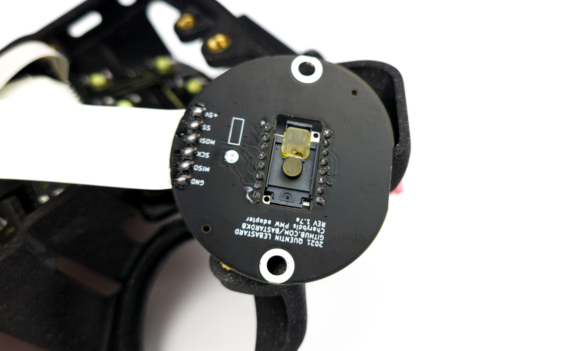
You may choose to remove the Kapton tape, or leave it on. It doesn’t make a difference during use of the trackball.
Guide the sensor through the hole in the 3d print:
Reinstall the lens: 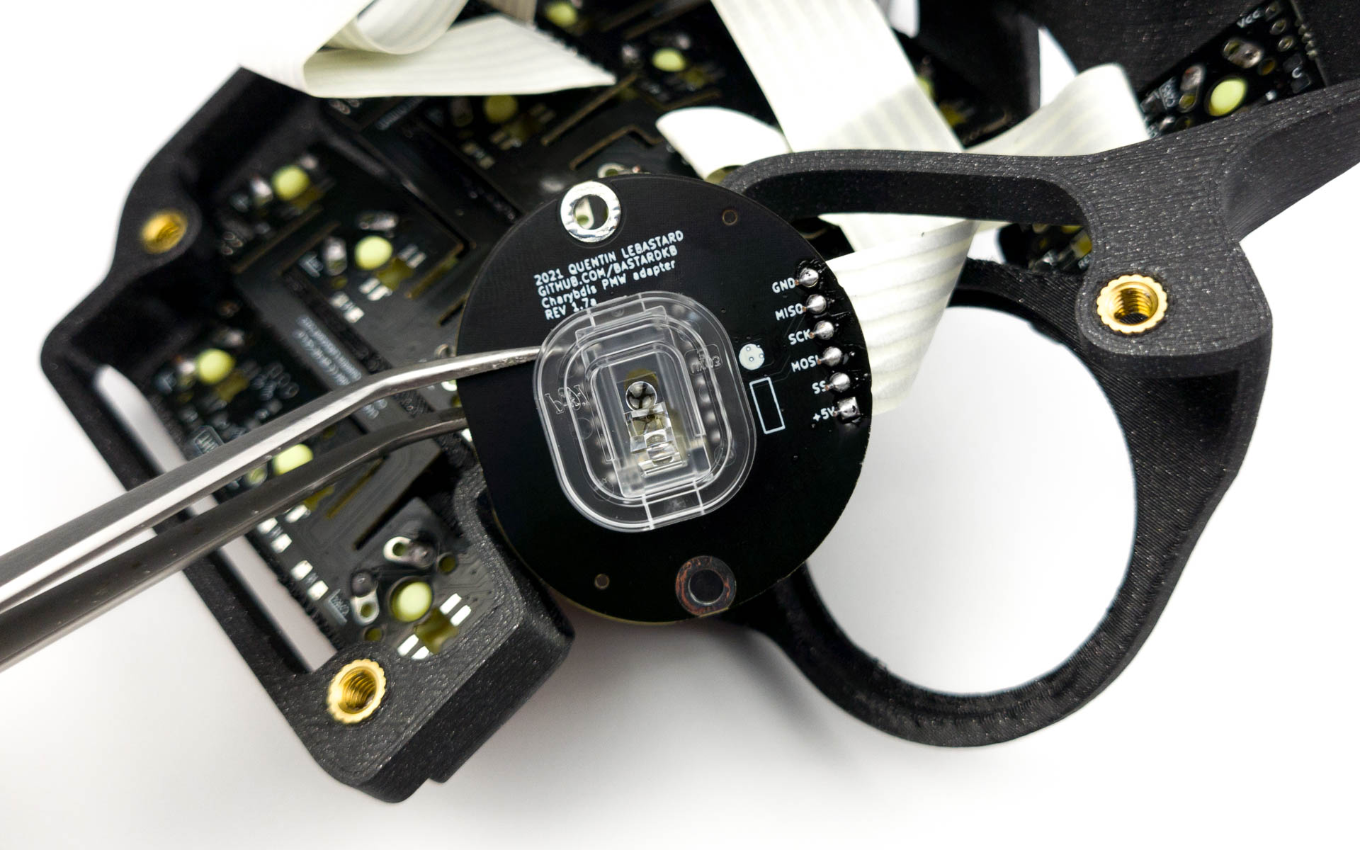
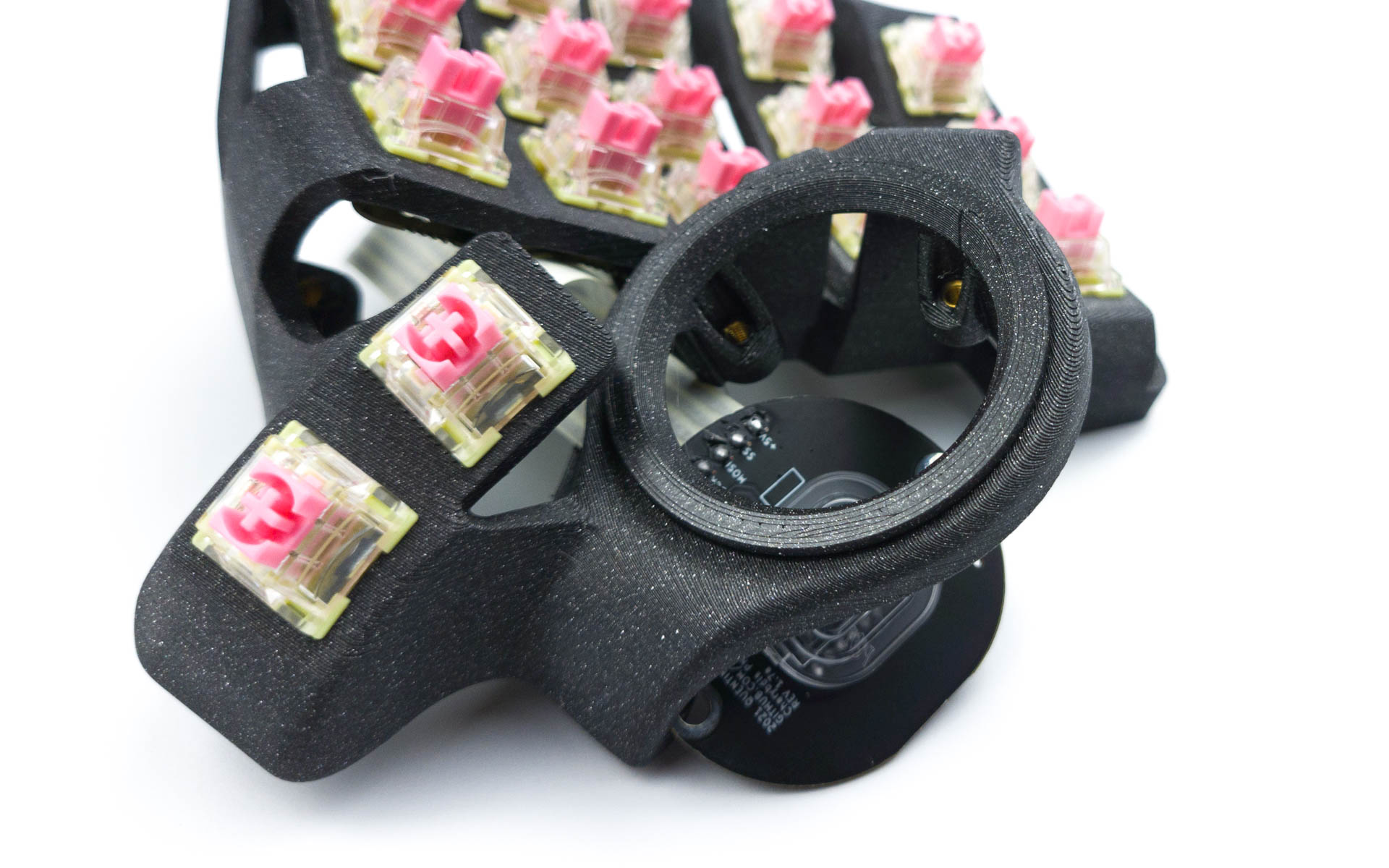
Installing the 3d holder assembly
Top part
For the following step, please prepare:
- top sensor assembly
Slide the left side of the top sensor assembly into the case:
Push in the right part:
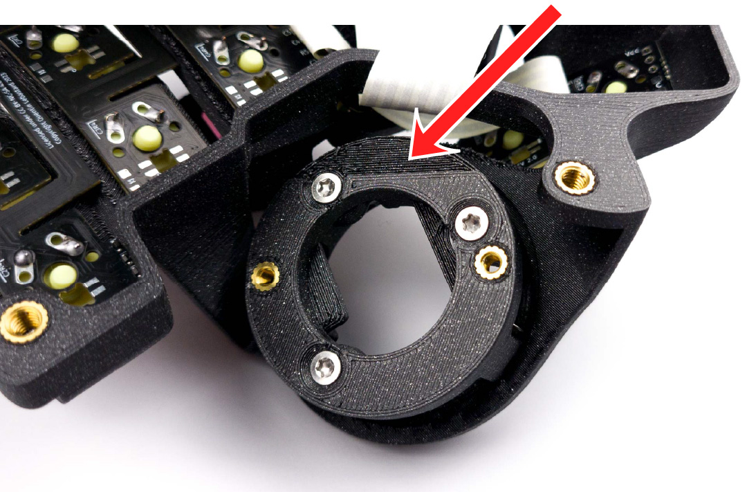
Bottom part
Depending on your kit, the bottom housing might look slightly different. Install the screws to match the picture below.
For the following step, please prepare:
- right keyboard assembly
- bottom sensor assembly
- m3 screw (x3)
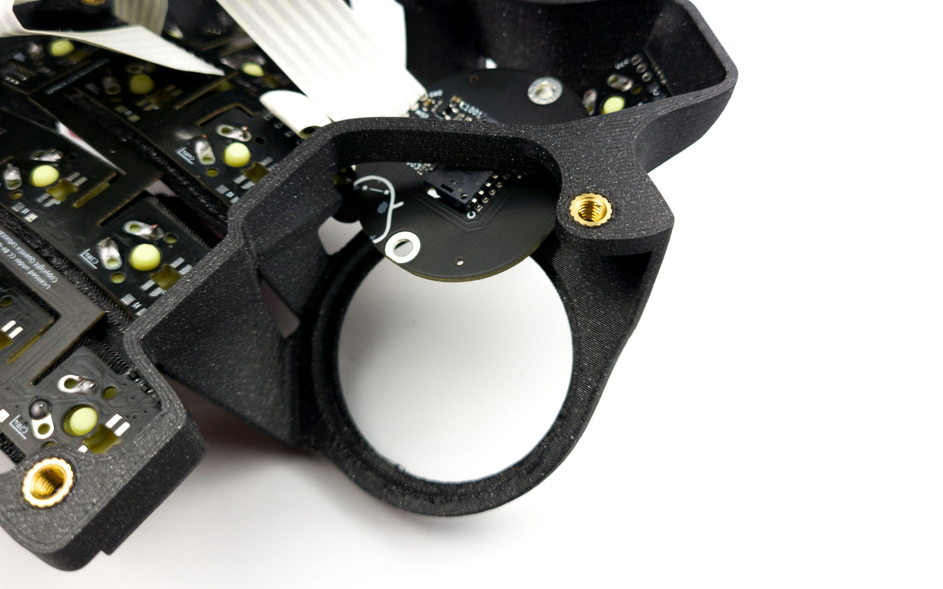
Install the bottom sensor assembly:
- Screw in the 3 screws
- Make sure the the part is oriented towards the keyboard. Use the picture below for reference
- Make sure it’s tight, but do not overtighten - you might damage the print
- The whole assembly should not move at all
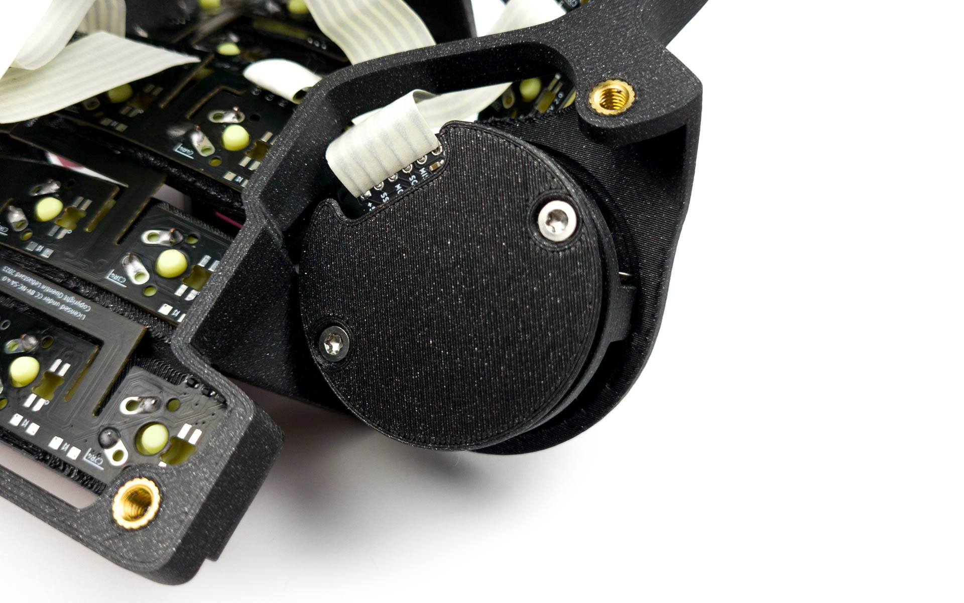
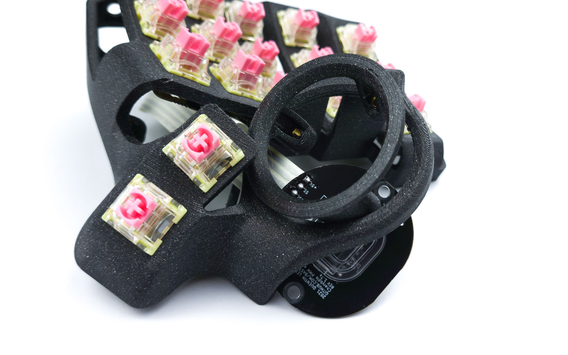
Installing the sensor PCB and protective cover
In this final step, we will screw in the sensor PCB and its protective cover.
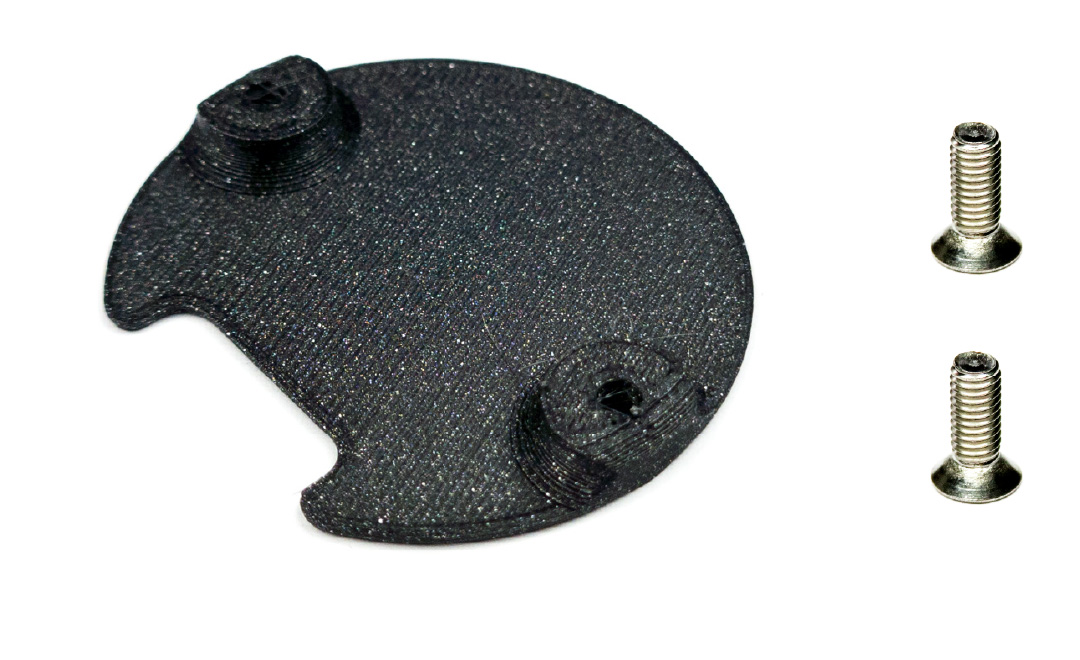
For the following step, please prepare:
- right keyboard assembly
- sensor cover
- m3 screw (x2)
Install the sensor PCB and cover:
- Install the sensor PCB on top of the holder, aligning the two holes of the PCB with the two holes of the holder
- Screw in the sensor PCB using 2 M3 torx screws
- Use the picture below for reference