Table of contents
- Table of contents
- Installing the per-key RGB
- Soldering the audio jacks and reset buttons
- Preparing the trackpad assembly
- Connecting the trackpad ribbon cable
- Connecting the trackpad assembly
- Test the PCB
- Soldering the switches
- Customize your firmware
Installing the per-key RGB
If you ordered a kit with per-key RGB, we will start by installing those. If you don’t have LEDs, you can skip to the next section.
The LEDs need to be installed in a very specific way. Read the following instructions carefully first, and then install them. If you don’t, they will not work!
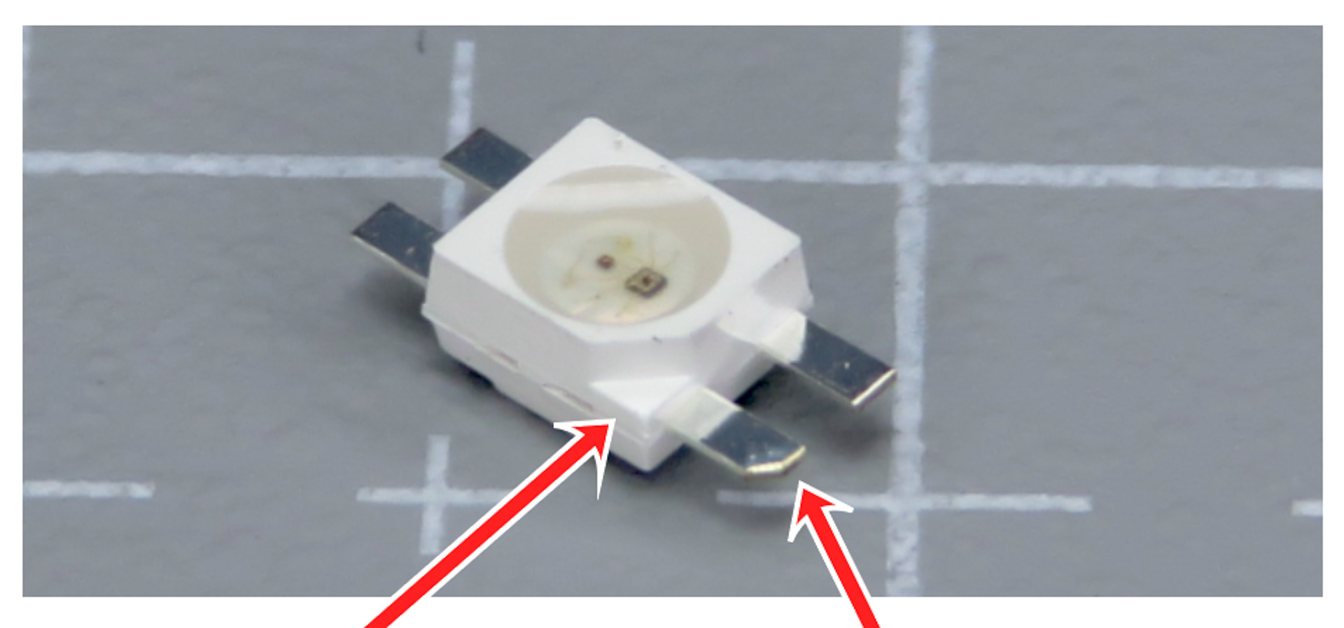
Inspect the LED: there is one of the pins that has a slight chamfer in it. The plastic casing also has an indent. This is the GROUND pin.

- Inspect the PCBs: for each LED footprint, there is one pin that has a white dot next to it
- All the LEDs are installed in the same direction. If one dot is obscured by the silkscreen, just install the LED the same way as the others
- We need to match the chamfered pin of the LED, with the marked pin on the PCB
The LEDs are sensitive to heat. Stay at most 2 seconds on each pad. If that doesn’t work, try slowly increasing the temperature of your soldering iron.
- Install the LEDs
- Solder them pad by pad
- Go through the LEDs one by one

Soldering the audio jacks and reset buttons
- There is only one way the components can be installed, so there’s no risk of messing up!
- Solder in the audio jacks
- Solder in the reset buttons- When installing the reset button, take care not to short the pads to the vias nearby.
- The vias are the round metal holes.

Preparing the trackpad assembly
Install the 5 screw inserts:
- Set your soldering iron temperature to 200 degrees Celsius
- To make it easier, use pliers to hold the 3d print
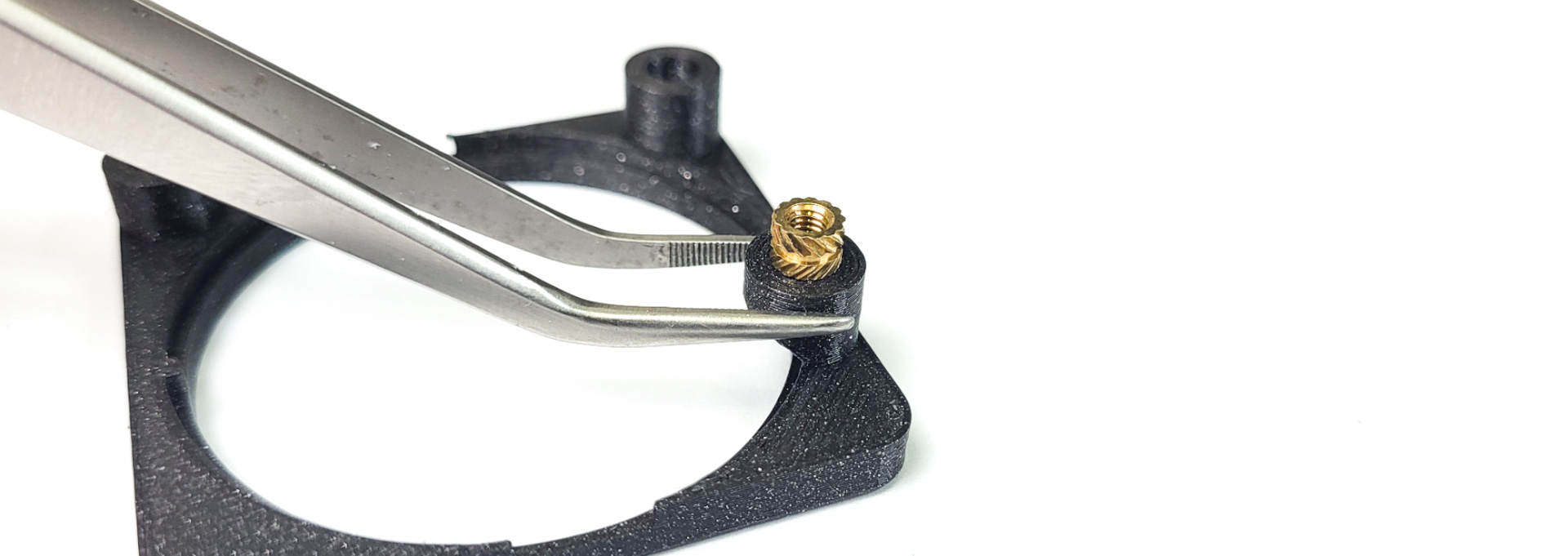
- Using the soldering iron, place the heated insert inside the hole
- Apply little to no pressure, let the gravity do the work. Otherwise, you might push them too far
- If the insert doesn’t fall into place, you can slowly increase the temperature, but don’t go over 300 degrees
- Once the insert is 2/3 of the way in, stop
- Flip over the print and gradually push it against a flat surface, to make the insert flush with the print
- Move the parts aside and let them rest, while they cool down

The kit comes with grey screws. If you ordered a case, you will also get black screws. For this step, use the grey screws.
- Install the first part of the 3d print holder on the right side PCB. Do not screw it in completely, we will do this later.

- Slide the trackpad into the assembly. Align the notch, just like on the picture below (at the bottom)
- Screw in the retainer

Connecting the trackpad ribbon cable
Please note: you do not need to desolder any resistors on the trackpad. Just use it as it came in the kit!
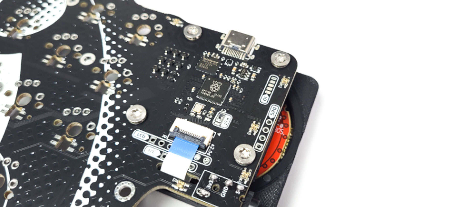
- On the Right side of the keyboard,
- Open the FPC connector
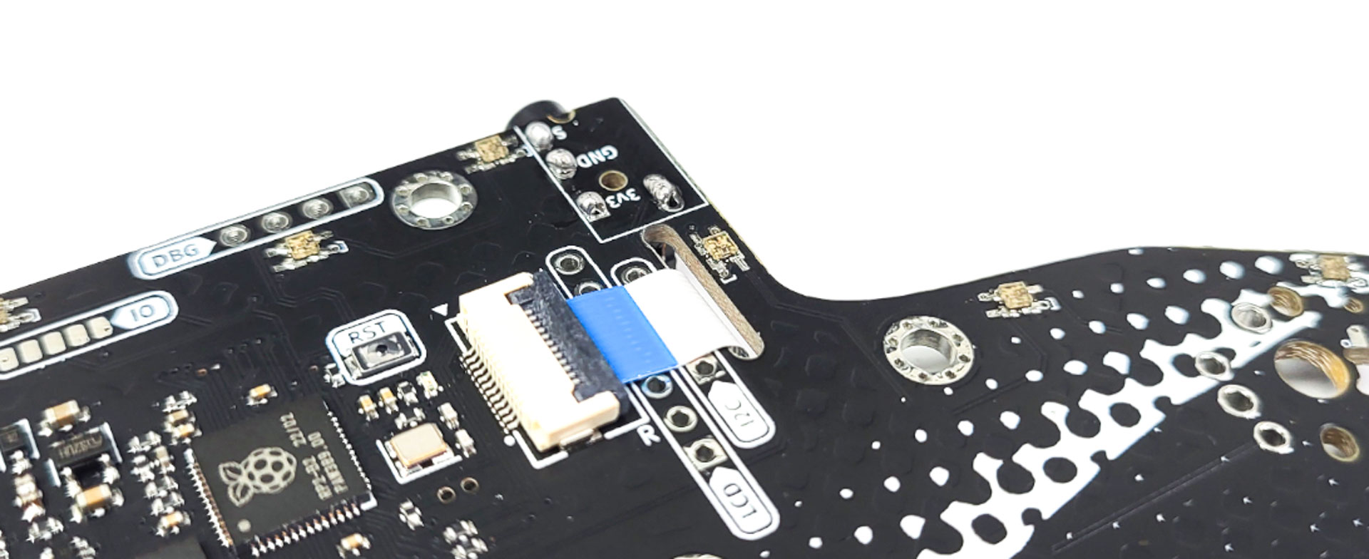
- Slide the cable in like on the picture below
- Close the FPC connector
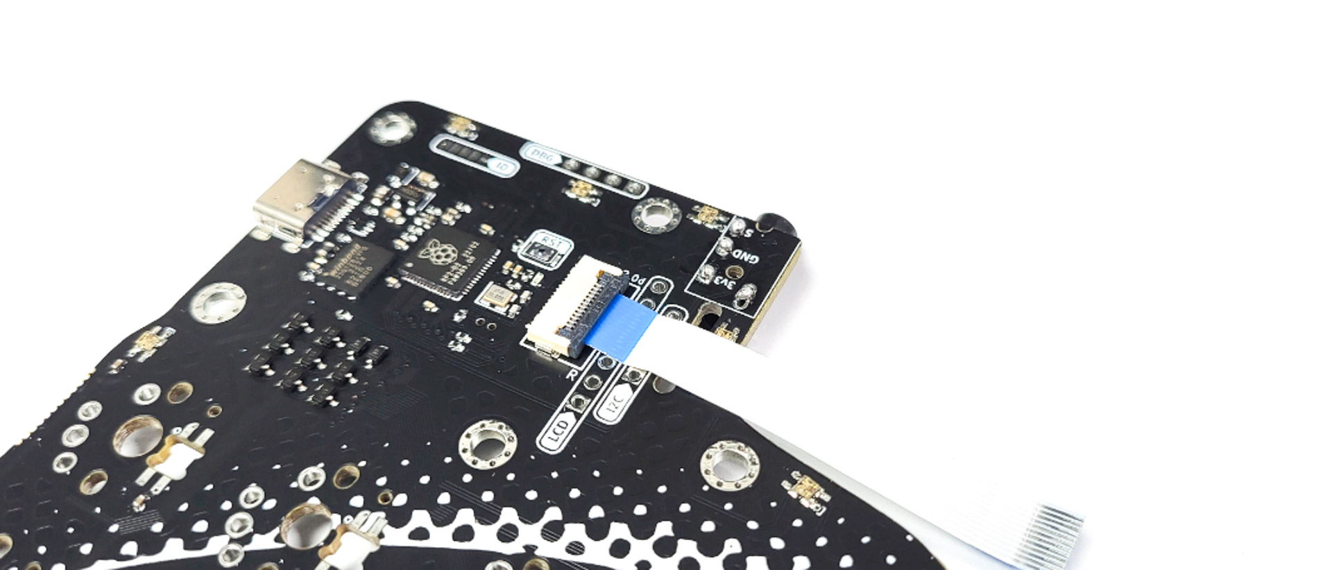
- Slide the other end of the cable into the slot
Connecting the trackpad assembly
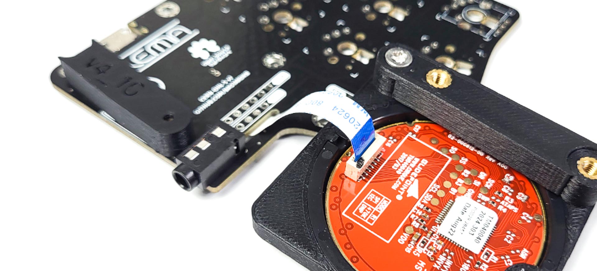
- Connect the other side of the ribbon cable into the trackpad assembly
- Make sure you install it like on the picture below - the blue part on the same side as the black dot
- If you don’t have a case, screw in the 4 screws and tighten them like on the picture below
- If you have a case, read the instructions in the case page, after installing the switches.
Test the PCB
This step is optional, but highly recommended.
- Connect the keyboard to your computer - it comes pre-flashed with QMK
- Check that the cursor moves when you use the trackpad
- Using tweezers, short 2 pins of a switch. Check that it registers
Soldering the switches
Solder in your switches of preference.
Customize your firmware
You’re all done!
Head over to bstkbd.com/custom to customize your keyboard to your needs.
If you need any help with it, make sure to hop on the discord : bstkbd.com/discord