Table of contents
Testing the PCBs
Now is a great time to function test the assembled PCBs, as any troubleshooting steps you might need to complete will be much easier to do while the plates are still outside of the case.
The TRRS connection will not work yet, as only ony one leg of the jack is connected. You can test this part later.
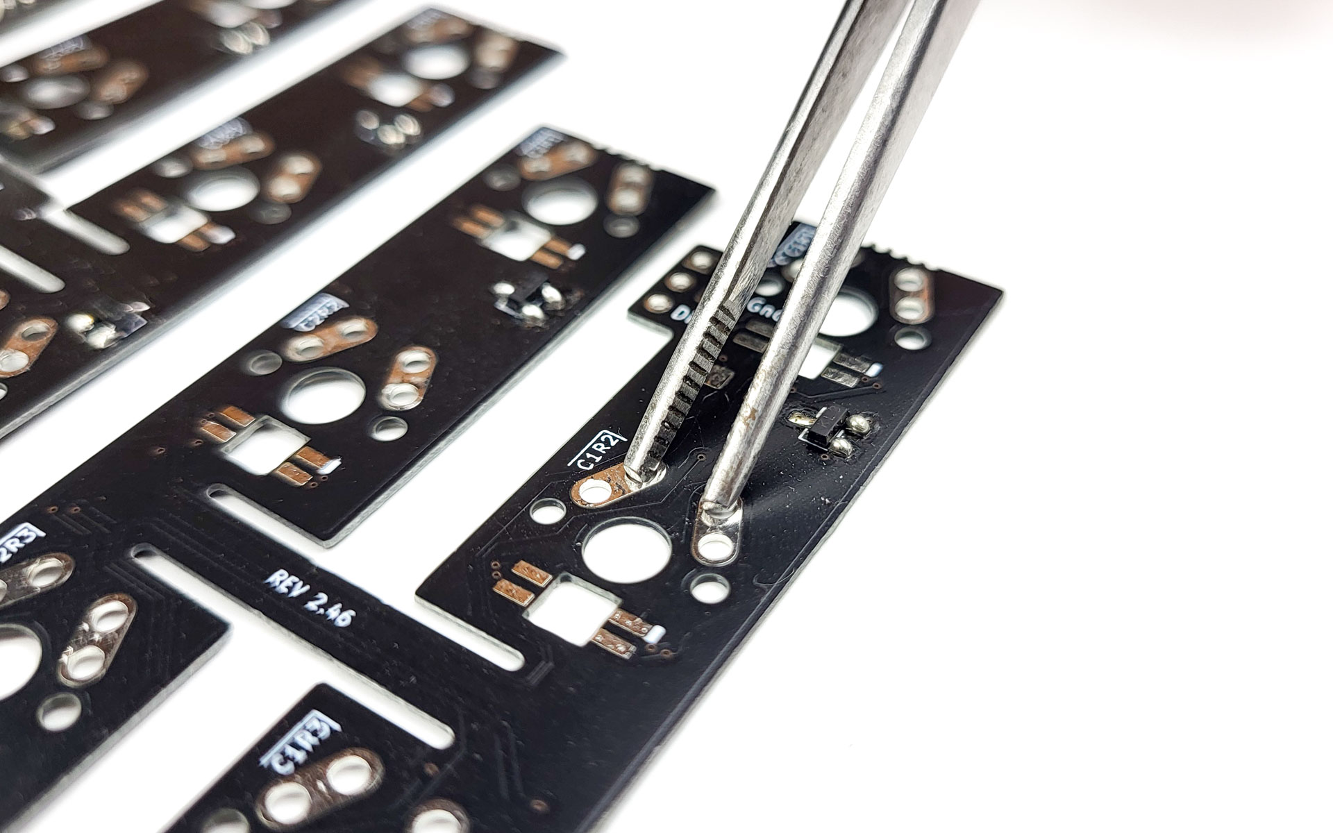
For the following step, please prepare a pair of tweezers that are conductive. If you don’t have any, you can also use a piece of wire, or a single switch.
Testing the LEDs
If you have installed per-key LEDs, let’s start with testing those. If you don’t have any per-key RGB installed, you can skip to the next section.
- connect one half to your PC via USB, and observe the LEDs:
- do they all light up?
- can you see all LEDs show bright red?
Does everything look fine? Great, go ahead with testing the switches.
If not, reflowing the pads of the LEDs not working should do the trick. Please see Troubleshooting for details.
Testing the switches
To test the switches, we are going to use the VIA interface. All Bastard Keyboards come pre-flashed with VIA, so you don’t have to flash anything.
The default firmware requires the USB cable be connected to the right side of the keyboard. This means that when testing the left side, the keys will be reversed.
Open VIA - please note this only works on chromium-based browsers like chromium, edge, chrome.
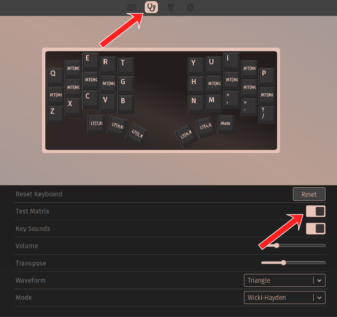
After connecting to your device, switch to the key tester page using the stethoscope pictogram, then activate the “Test Matrix” option. Now, you can connect each pair of switch pads in turn, using your tweezers, a wire, or a switch inclined enough.
Did all the keys light up in VIA? Great, proceed to case installation! Not quite perfect yet? Don’t worry, proceed to the Troubleshooting section!
Introduction
Now that everything is connected together, the next step is to install the switches and the PCBs into the case. The process is exactly the same for both sides, so we will detail only the Scylla side (without trackball).
While in theory you can install the switches in any order you like, we outline below what we found out works best.
The case is made of plastic, and will melt if you touch it with your soldering iron. Be careful!
We will detail only the left side, as the right side is the same, but symmetric.
Installing the switches
We will start by detailing a technique to install the switches, and then in which order they should be installed. Please read this whole section first to familiarize yourself, and then proceed to the installation. Otherwise, the process might be more complicated.
When installing the switches, use the following technique:
- press the PCB against the case, and try to align it as much as possible
- from the other side, push the switch into the case hole
- make sure the pins align into the PCB’s holes
- make sure the PCB is flush against the switch. If your switch has side pins, you may have to push it a bit harder
- solder the two pins of the switch
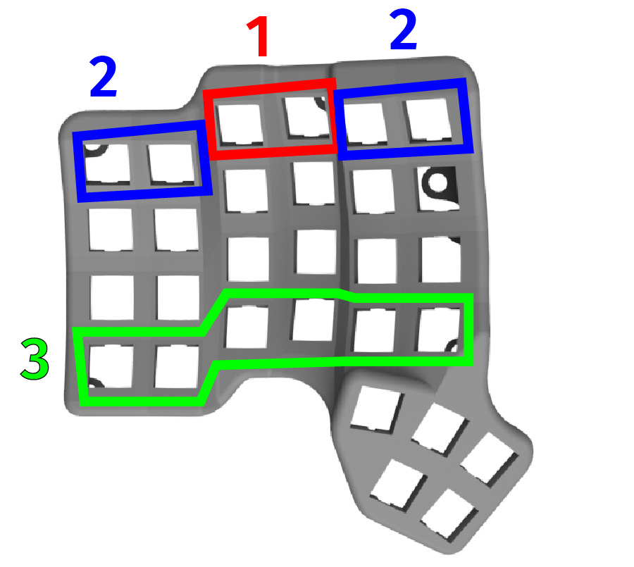
- start with the top two switches (labeled 1, in red on the picture)
- continue with the outer four switches (labeled 2, in blue on the picture)
- continue with the bottom six switches (labeled 3, in green on the picture)
- finally, install the rest of the switches