Table of contents
Introduction
The Splinky and the flexible PCBs are ready. Next we join them.
The shield assemblies are not reversible. We will do the left side first, then the right.
Left side
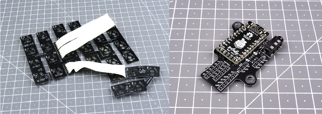
For the following step, please prepare:
- Splinky shield assembly (left)
- flexible plates assembly (left, with 5 keys on the thumb cluster)
Inspect the shield assembly: there is a MATRIX label, with a 5-pin and a 6-pin connector. We will connect it to the cables of the flexible PCB assembly.
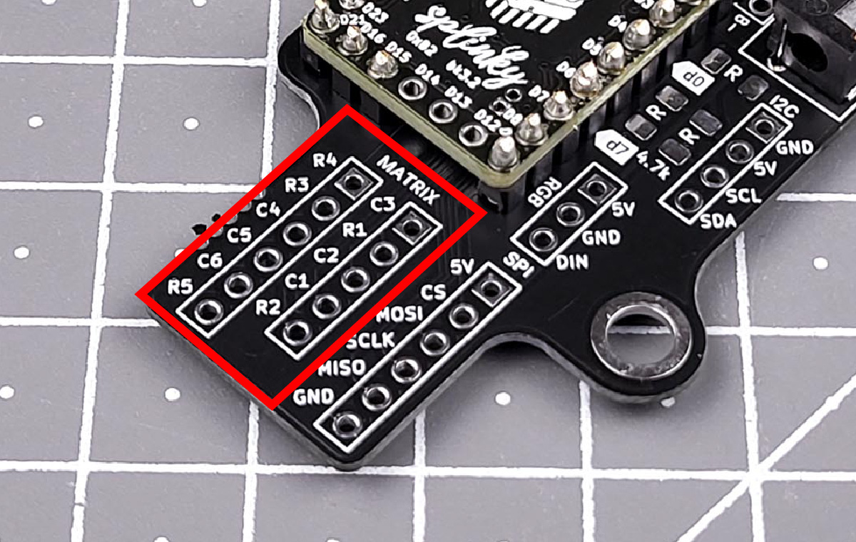
Solder the cables on the side shown in the pictures - the other side is much harder to route into the case. The ribbon cables are fragile; once they are soldered, avoid bending them.
Install the cables coming out of the flexible PCB assembly into those connectors, and solder them.
Once installed, avoid bending the cables. They’re fragile and can break. 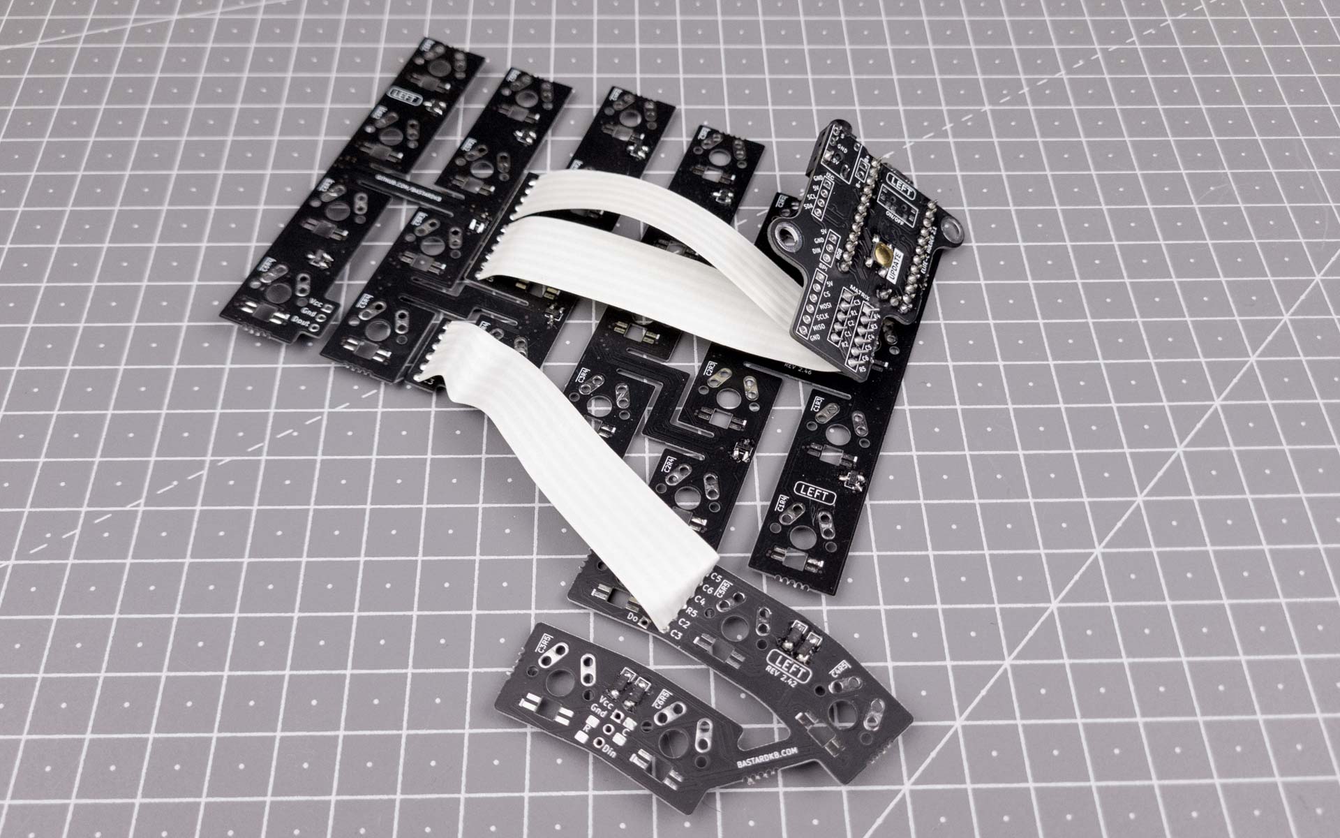
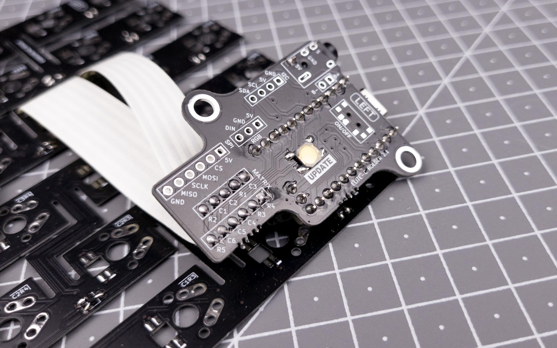
Left side - RGB
This step is optional, if you have per-key RGB.
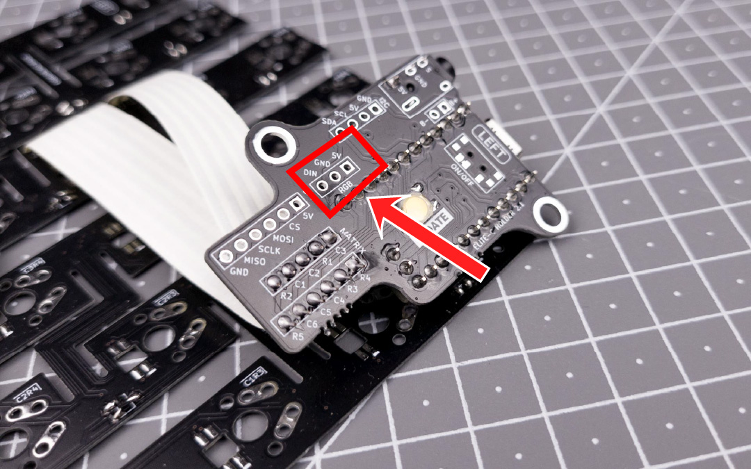
Solder the long ribbon cable coming from the plate to the RGB header on the Shield PCB. Use the picture below for reference.
Right side

For the following step, please prepare:
- Splinky shield assembly (right)
- flexible plates assembly (right, with 3 keys on the thumb cluster)
Inspect the shield assembly: there is a MATRIX label, with a 5-pin and a 6-pin connector. We will connect it to the cables of the flexible PCB assembly.

Solder the cables on the side shown in the pictures - the other side is much harder to route into the case. The ribbon cables are fragile; once they are soldered, avoid bending them.
Install the cables coming out of the flexible PCB assembly into those connectors, and solder them.
Once installed, avoid bending the cables. They’re fragile and can break.


Right side - RGB
This step is optional, if you have per-key RGB.
Solder the long ribbon cable coming from the plate to the RGB header on the Shield PCB. Use the picture below for reference.
